标签:Building Development Workbench wires power will circuit vehicle your
https://www.rapid7.com/blog/post/2017/07/11/building-a-car-hacking-development-workbench-part-1/
Introduction
There is a vast body of knowledge hiding inside your car. Whether you are an auto enthusiast, developer, hobbyist, security researcher, or just curious about vehicles, building a development bench can be an exciting project to facilitate understanding and experimentation without risking possible damage to your vehicle. This is a perfect project for people of a wide range of ages and skill levels. Even if you have never worked on a car before, or you do not feel like your Electronics-Fu skills are strong, there are dozens of blogs, training videos, and reference guides on the internet that can supplement the information in this guide.
This the first part of a three-part series. Part one covers how to build the physical bench. Part two will discuss how to read wiring diagrams and serve as the primer to part three, where we will re-engineer common circuitry.
A car hacking workbench consists of the critical electronics that control the vehicle, plus bits and pieces of the electrical harness. This is like a neurosurgeon operating on a heart, brain, and spinal cord outside of the human body, except more accessible to the squeamish. Within this guide, we will explore:
- Finding a suitable vehicle
- Extracting the critical components
- Building and powering a workbench
- Re-engineering circuits and sensors
- Experimenting with your bench
You can adapt the following steps to any vehicle. We chose a 2006 Dodge Stratus, 2.7L, four-door sedan. This vehicle has a Controller Area Network (CAN) Bus interface accessible through the On-board Diagnostics (OBD-II) port. By reassembling the electrical components, we can connect to the vehicle's “brain” through the OBD-II port, and experiment with traffic on the CAN Bus.
Note: Some vehicle manufacturers do not share standards between production lines, or even between builds of the same make or model that are a year apart. Find information, such as wiring diagrams and parts, that are specific to your vehicle. For example, If you are working with a heavier class of vehicle, it may interface with the CAN Bus through a J1939 diagnostics port instead of an OBD-II connector. You may also find that newer hybrid vehicles have different power voltages that you need to be aware of while constructing your bench.
Tools
This project is going to take more than just a simple screwdriver and a pair of clippers. This is not a complete list, but here are some tools that you may want to have on hand:
- Phillips and flathead screwdrivers in assorted sizes
- Loppers and/or wire cutters
- Basic set of standard and metric socket wrenches, plus extension bits
- Wire strippers
- Safety equipment (gloves, goggles, light-weight face mask)
- Voltmeter (a cheap basic model is fine)
- Multimeter
- Flashlight
Important Note: When working in an old and dirty car or environment (such as a vehicle in a junkyard), WEAR A DUST MASK! Removing an electrical harness can expose you to heavy amounts of dust and bacteria. When the electrical harness is out of the car, wipe down all the components and cables with a small amount of a mild soap and water to reduce the risk of illness.
Time Requirements
Anyone with a moderate amount of mechanical or electrical knowledge could complete this project over a weekend (16-20 hours). Those with more limited knowledge of these two key areas may need two weekends: One to remove the physical components and a second to reassemble and test.
Part Requirements
No two vehicles are identical; however, all vehicles possess some commonalities. Your build may not require every component mentioned in this guide, but you should be at least familiar with the following terms:
- Power Distribution Center (PDC) – Channels power from the battery into the rest of the vehicle.
- Junction Box (also known as a fuse panel) – Fuses protect the wiring system. If a component faults and causes a power surge, the fuse will sacrifice itself to protect the wires in your vehicle from melting and causing severe damage.
- Powertrain Control Module (PCM) – Controls input and output to over a hundred various sensors placed on the engine and throughout the vehicle, then injects data into the CAN Bus, the vehicle information network. Generally, the PCM is a combination of the Engine Control Unit (ECU) and Transmission Control Unit (TCU). This is important to know, as wiring diagrams can introduce confusion by using PCM, ECU, and TCU interchangeably.
- Instrument Cluster (IC) – Located in the dash, this device is monitored by the driver and contains indicator levels, speedometer, RPM gauge, etc.
- Immobilizer (sometimes referred to as the skim module) – Connected to the ignition switch in the steering column, the immobilizer authorizes the key in use while starting the car. If the immobilizer is missing, unpowered, or the wrong key is in use, then the car will not start.
- Body Control Module (BCM) – Controls the functions associated with various circuits of the vehicle's accessories and communicates via the CAN Bus. May share a housing with in junction box.
- Ignition Switch & Key – The keys, tumbler, and power feed that start the vehicle.
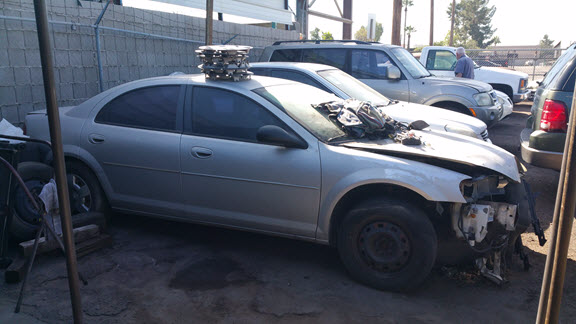
In order to source a vehicle to use for this project, we recommend that you call junkyards in your area and ask if they have any wrecked vehicles that still have all their components, electrical harness, and keys. Yes, it is that simple.
Pro Tip: make friends with the working professionals at the junk yards. I am not saying have them over for dinner or invite them to your weekly poker game, but explain your project and what you are looking for. Vehicles regularly come into junkyards following an accident. So, let the junkyard know what you're looking for in a vehicle. If they don't have what you're looking for, they may call you when something arrives.
As for the type of vehicle that you are looking for… that is completely up to you. If you just want a workbench to train on, then any vehicle newer than 2005 will do. Just remember that larger-class vehicles, such as class 3 or 6 , may use a J1939 connector instead of an OBD-II.
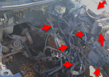
Step 2 – Removing the Electrical Harness
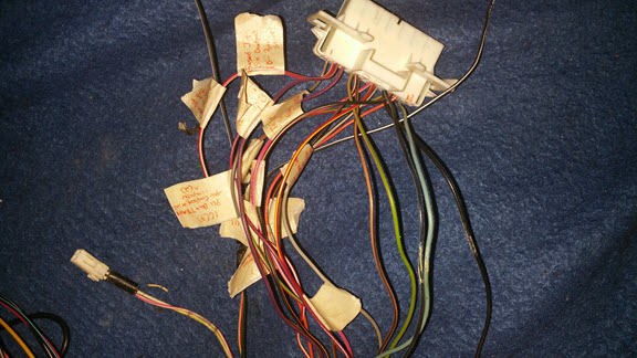
First, and most important: DO NOT CUT ANYTHING! At least not yet, anyway. Before you grab the clippers and go to town hacking into wires, I suggest taking the time to identify and label components, connectors, couplings, wires, and sensors. This will save an incredible amount of time in the long run. If you skip this step now, when everything is out of the vehicle and you're building your workbench later, you get to play a not-so-fun game called, “Where Does This Go?” (You may notice there aren't any pictures supporting this process) I played the game, and it's not fun. I can positively recommend: label everything before you begin! Even if you don't know what every piece under the hood is, marking items with a simple A, B, C pattern now can significantly reduce confusion in the future.
Second, take detailed pictures of connectors while they are still connected. If you choose to forego pictures, don't worry. Most connectors are designed to fit in only one socket and in only one direction. Also, for the ease of maintenance, engineers use couplings to attach wiring extensions from sensors and components to the main electrical harness.

After completing the labeling and identification process, start to remove the components and wiring harness. There are two practical ways of removing everything that you need.
The first way is to simply unbolt and disconnect everything from the front of the engine compartment and unbolt anything in your path until you reach the steering wheel, then remove everything in one long piece. There is a tiny hiccup in this course of action: getting the cables out in one piece may require passing everything through a hole in the vehicle's firewall, which may be smaller than some of the major components. To make this process simpler, disconnect any unit that will not fit before passing the cables through the hole, pull the cables just far enough, and reconnect the unit when the last connector is through the other side. This way you won't forget how something was connected in the first place.
The second way is to cut the entire system into two large pieces: one consisting of everything under the hood and a second made up of everything within the vehicle. This method makes it easy to remove all pieces from the vehicle, but will require that you reconnect two pieces with electrical caps or other types of connectors.
Now, grab your safety gear and tools, roll up your sleeves, and get to it. Just a heads up, do not wear something that you will want to wear ever again. This can be an extremely dirty job. Mike Rowe would be proud. Furthermore, if you cherish your health, even just the tiniest bit, wear a dust mask.
Step 3 – Initial Testing
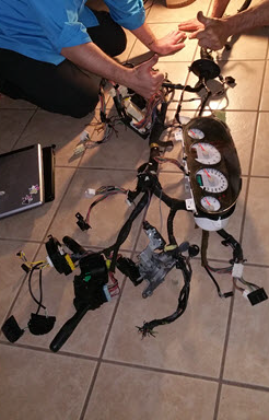
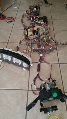
Now that everything is out of the car, make sure that it can receive power. If you cut the harness into pieces, you will need to reattach the cut wires. Reconnect the harness to the instrument cluster, PDC, PCM, BCM, and ignition systems. At this point, you can just lay everything out across a large flat surface.
Powering your harness is different from normal power management in a vehicle. Some components can be directly powered from the battery and others wait until the car is running. Plus, when the car is running, everything is powered from the alternator, which is an AC circuit. Instead we will need to use power from an outlet, which is a DC circuit. Luckily, we are not powering an entire car, so we can replicate the battery's DC connection through the Power Distribution Center (PDC).
Car batteries generally hold approximately 12.6 volts (or slightly higher) when the vehicle is not running, and will shoot up between 13.7V to 14.7V when running (except for hybrid or electric vehicles, which are completely different ball games, and too much detail for this section). If you have a variable power station, you are good to go, but portability and expense can become an issue. During this project, I used a generic variable DC power adapter cranked up to 12V at 1.2 amps and did not experience any trouble powering the harness and components. You may have to strip the ends of the adapter and either solder the wires (safe option) or like me, clamp down partially stripped wires with alligator clips (not recommended, but okay for initial testing only). Screw terminals are also a safe option, and perhaps the most versatile power management utility if you are unsure how you want your bench to look at the moment.
To complete the power connection, find the positive terminal on the PDC, usually indicated with a red plus symbol. Inside the PDC there should be a metal bar that transfers current to the various fuses and relay circuits, and in turn to the rest of the vehicle. Connect the negative (grounding) wire of the adapter to a vehicle ground. If you are unsure if the circuit is complete, check for continuity with a voltmeter by connecting one probe on positive and the other on cables (which we recommended that you label earlier) to ground. Keep changing the probe from one ground point to another until the voltmeter shows continuity and/or holds a tone indicating the completed circuit. Finally, plug in the 12V DC power adapter to the power source (i.e., a wall outlet).
Provided the ignition system was hooked up, power is available, the immobilizer is connected, and the keys are in the ignition switch, when you turn the key, the instrument panel should light up. Just about every sensor available through the instrumentation cluster will indicate there's a problem. Take a deep breath, it's normal: obviously, a missing car engine will cause warnings!
If you didn't get power, check connectors, couplings, and fuses first. If power still isn't going through the system, grab your handy-dandy multimeter and check all available grounding wires. If you have never used a multimeter to check volts, resistance, amps, or continuity, then I suggest watching this video from Ratchet and Wrenches.
Switch your multimeter into continuity mode and touch each prong to the positive and grounding (negative) wires of your adapter. If you do not hear a beep, the circuit is incomplete. Move the negative prong of the multimeter around to various grounding points until you hear a beep. Now move your grounding (negative) wire from your power source to that new location. This should correct the problem.
Important Note: When power is available, and the instrument cluster is active, disconnect the DC power adapter from the power source, THEN the PDC and grounding point. Failure to do so could create a spark, shock you, or possibly start a fire in a worst-case scenario.
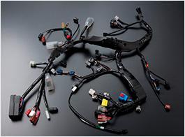
Step 4 – Unwrap & Thin Out the Electrical Harness
Now that you have power to the main components, start removing the black electrical tape and fire barrier from all wires in the harness. I recommend wearing gloves, as the stickiness of the tape can tear into your hands after a while. You may be tempted to cut into the tape surrounding the wires, which is fine, but make sure that you do not cut any of the wires during the process.

After stripping the tape from the wires, spread the electrical harness and connected components as far apart as possible. Examine the harness for any connectors that are not plugged into any equipment. These connectors are not needed to complete the bench, and can be removed. While clipping connectors, leave a 6-8” pigtail. You do not want to clip the wires at the base of the connectors; depending on how you develop your workbench beyond this guide, you may need one of those connectors in the future.
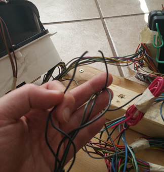
Now that unnecessary connectors are gone, remove excess wires that are not connected to anything. This will help thin out the harness and keep the cable management process clean.
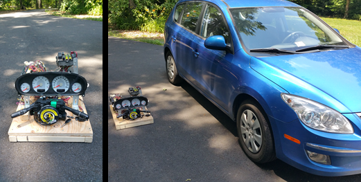
Step 5 – Design & Build Your Workbench
This step in the process is COMPLETELY YOUR OWN! That said, you may have space requirements. While I was building my workbench, I wanted it to be portable and not too bulky, so I could ship it across the country for peers to learn from and practice on. Pictures available online through web searches show that some people have the system stretched out on a lab table, a large board, or even the garage floor. Others have used Lego and Erector sets to build vertical mounting racks. My entire bench had to fit inside a large travel case, so there were height, width, and length requirements. No matter how you choose to build your workbench, leave enough physical space between components that both hands can easily work inside without a struggle.
Design, build, and then re-power the unit. If the instrument cluster lights up after turning the key to the start position on the ignition switch, you are good to go.
Ready for part two? Read it here.
This is part two of a three-part series. Part one covered how to build a development workbench. Part two of this series will cover reading electrical diagrams and serve as a primer for part three, where we will re-engineer common circuit types found in vehicles.
Electrical Diagrams & Re-identification
Technically, your bench is complete at this point, and you can connect an OBD-II to USB conversion device to start interpreting the CAN Bus. But where's the fun in that? Let's dig a little further into process. Even if you don't expand your bench, knowing how to read wiring diagrams is crucial when troubleshooting electrical problems in your own vehicle.
First, no two sets of wiring diagrams are identical. Individual companies have an internal standard, but there isn't an accepted industry standard for labeling diagrams. I found that Haynes and Chilton vehicle manuals are fantastic for maintenance, but are terrible for wiring diagrams. There is a reason for this negative review: Both Haynes and Chilton group vehicles by revisions of the vehicle's' design. For example, the workbench I built for this guide was a 2006 Dodge Stratus with a 2.7L engine, and the appropriate book that coincides with this vehicle is: Chrysler Sebring, Dodge Stratus & Avenger 1995 thru 2006 (Haynes Repair Manual). The problem I ran into was that the wiring generally changes every couple of years, sometimes yearly.
Wilson's diagrams allow you to select an exact year, make, and model, although there are other diagrams available. I found that Wilson's diagrams were accurate for the vehicle I was using. If you have access to applications for mechanics, or you are willing to pay for a license, those programs are incredibly thorough and list any parts that you may need from your local auto shop.
There is only one sure fire way to learn about diagrams, and that's hands-on. Let's examine a wiring diagram for the driver's seat belt indicator:
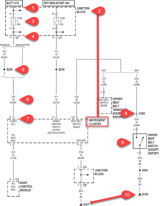
1. Power source. BATT A13 indicates that this is the thirteenth power source fed from either the battery or alternator, and is fed into fuse 7 on the junction block.
2. Equipment. The fuse in this vehicle is located within the junction block, but many vehicles have multiple junction blocks. So, check your diagrams and maintenance manuals for the exact name of the junction block. For example, the Wilson's diagrams refer to the junction block as the fuse panel attached to the BCM, while the fuse panel in the PDC is simply referred to as ‘PDC' to reduce confusion.
3. Fuse. Fuse 7 is a 20Amp fuse that transfers energy from the A13 circuit to connector C7 on pin 11.
4. Initial path of power. There is a lot happening here in the diagram. To continue the circuit, a pink and white (PK/WT), 20-gauge wire (See Item 6), transfers energy from connector C7's 11th pin, and the circuit is no longer A13, but rather F33. On a premium (luxury) vehicle, the pink and white wire follows a different path.
5. The S225 junction. This is a spliced wire. This is very common for initial power and ground wires.
6. Wire nomenclature. Read as fused circuit 33. 20-gauge wire. Pink and white in color.
7. Connection point. The energy of the circuit flows into the instrument cluster on pin 21.
8. The C303 junction. This is a coupling connector. Your maintenance manual may or may not inform you of the exact location of couplings. To determine what exact number of the coupling is, scour your diagrams for other indications of the coupling number. Identifying groups of wires can help identify the exact coupling. Example, C303 in my vehicle is the only coupling to have the following combination:
a. C303, pin 12, white and blue
b. C303, pin 13, green and red
c. C303, pin 4, black
I recommend using a marker to write the number on the sides of the couplings as you identify them.
9. Switch. Albeit labeled as a switch, I specifically highlighted this section for you to understand that these are the type of circuits for which we can replicate either by installing a switch of our own or directly grounding the wire.
10. The G301 and G302 junctions. These are grounding points. It is likely that the grounding points will also not be identified by maintenance manuals. As a recommendation, tie all the grounding points wire all the grounding points in your bench to one physical connection. All electrical circuits need a ground to be complete. Grounding all the points together will ensure that any redesigned components you add or manipulate in the future will be grounded accordingly and leave you free to focus on the interaction of the circuit.
If you have never seen wiring diagrams or traced an electrical path in a vehicle, this can be daunting. The wiring diagram pages can have many different components smashed into one page, the wires likely will change colors, and possibly run through multiple adapters. Let's further examine the diagram to understand how power flows through a simple switch process: the driver's seat belt.
After learning to read the diagram, we will discover how easy it is to manipulate the circuit itself. In the figure below, the green line highlights the path of the circuit:

1. The circuit for the driver's seat belt indicator starts on a light green and small red striped, 20-gauged wire originating from pin 24 of the instrument cluster and is designated as ‘grounded circuit 10.'
2. From the instrument cluster, the initial light green and red wire terminates at coupling 303 male end on pin 13. The corresponding female coupling continues the circuit as a light green and red wire to the switch located in the driver's seat belt clip.
3. As the driver clicks the seatbelt, the circuit is grounded. Grounding completes the circuit (the next section of this guide will cover how to replicate this type of circuit as well as variable resistors).
4. The flow is now changed to a black, 18-gauge wire and connected to grounding point 302, which was probably connected to the body of the vehicle.
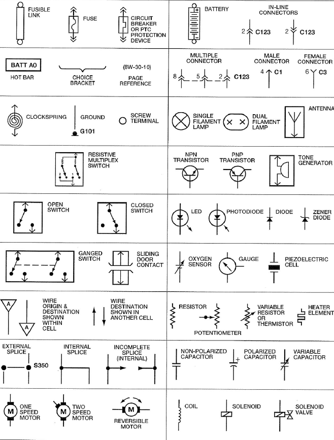
A good set of wiring diagrams should include a symbol identification chart, as seen here:
(Wilson Auto Electric, 2017)
References
Wilson Auto Electric. (2017, March 1). Wireing Diagrams. Retrieved from Wilson's TSB Database.
Welcome back to the car hacking development workbench series. In part two we discussed how to read wiring diagrams. In part three, we are going to expand on the workbench by re-engineering circuits and replicate signals used in your vehicle.
If this is your first time stumbling across this write up, I encourage you to check out the previous two parts to this series:
Part 1: Constructing a Workbench
Part 2: How to Read Wiring Diagrams
Re-engineering Circuits
There are hundreds of sensors and switches on a vehicle. It would be impossible to describe how to re-engineer all of them, but there are a few types of circuits that are reoccurring. This section will describe two common types of circuits that you may want to add into your workbench.
Switches

Just like a light switch on the wall, a vehicle switch has an open and closed state. In the open state, the circuit is not complete and the light (or sensor) is in the off position. In the closed state, energy traveling down the line is connected to the ground point. It is a complete circuit and the light (or sensor) is in the on position.
Let's explore the implementation of a switch in a real case scenario using the seat belt diagram above.
An illuminated 12v switch is a great starter circuit if you are unfamiliar with basic circuitry. There are three connection points to the switch pictured below:
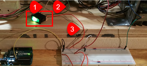
1. This is the RD/LG wire from pin 24 originating from back of the instrument cluster and connected to prong 1 of the lighted switch.
2. This green wire was added to the system and runs directly from the second prong of the switch to the PDC, as this is supplying the workbench with a 12V power supply.
3. The third prong of the 12V switch connects to ground. In the picture above, the orange wire is fed into the negative rail of a breadboard; however, it could have been directly linked to any available grounding point if it completed the circuit. A breadboard is a plastic electrical distribution tool used for prototyping circuits and can be purchased from electronics stores at a fairly cheap price.
Variable Resistor (Potentiometer)

Variable resistors channel power through a media, where the voltage of that power source can change. This process of changing voltage levels can be controlled using a potentiometer. Therefore, by substituting potentiometers for dials and sensors, we can replace the sensors that we left behind on the vehicle. For this example, we are going to control the fuel gauge using a potentiometer.

1. I used an Arduino Uno to provide a battery-drive, 5V signal to pin 1 of the potentiometer; however, you could use a power source from the chassis and achieve identical results.
2. Pin 2 is connected to the instrument cluster's pin for the fuel gauge.
3. The third pin is connected to ground. Pictured, the third pin jumps and connects to the breadboard's grounding rail, but could have just as easily been connected to any ground point directly.
With the workbench and the key in the on position, the instrument cluster will read the voltage from pin 2 of the potentiometer and adjust the gas gauge accordingly. So, by turning the knob on the potentiometer back and forth, we can adjust the fuel level.
Pitfalls and Shortcomings
Let me save you from going completely bonkers later by explaining some of my difficulties in this project:
1. It was working before. Why will it not work now?
You have either entered the Twilight Zone, or your circuit is no longer grounded. When I was building my bench, I didn't know what I could and couldn't cut, because of all the tape and fire hose wrapping on the electrical harness. As described earlier, I recommend removing these wrappings. However, I was not careful enough, and accidentally sliced into wires that were necessary to complete circuits that I tested later. After initial testing looked good, I moved the wires out of the way, only to find that the circuit didn't work anymore. Fortunately, it's a quick fix: just trace the wire and splice the broken pieces together. Another fault that occurred a couple of times was when an exposed (barren) wire would accidentally ground against something that it wasn't supposed to, so wrap any exposed splices or joints.
2. What is this and where did it come from?
I will definitely go back and do this project again. But, I will make sure that I label absolutely everything! I know that I spoke about labeling before, but here are some quick suggestions to help the labeling process:
a. At every connector, label where it came from or where it was connected (e.g., “Right driver door,” “AC ventilation switch,” or “In cabin on floor, towards shifter.”
b. When cutting cable veins (or removing a connector that is no longer needed): label both sides of the wires were cut with a matching 4 or 5-digit number. This will ensure that you know exactly where the wires came from and ease the workflow of repairing circuitry in the future.
c. Black cables are usually grounding wires. Many of them are connected and then tied directly to the body of the vehicle.
3. Is adhesive tape your friend or enemy?
Removing the tape from the harness was easy, but time consuming. The worst part of the entire process was the stickiness. No matter if your vehicle is 1 year old or 15 years old, the tape will be sticky. The tape residue will eat at your hands, embed itself in your clothes or hair, and be messy. I suggest wearing disposable gloves, tying your hair back (if needed) and wearing old grubby clothes. Now, if you think that sounds horrible, try using tape for labels… ha! Tape can go over the sticky residue of previous wires, but tends to lose its own stickiness when applied over dirty wires. Clean the area you are going to apply tape to first.
Bench Complete. Now What?
It's not just a fancy 40lb paperweight. It's a learning tool and developers' playground. If you have never connected to a vehicle CAN Bus, now is the perfect time; however, you are going to need a few items first. Most cars don't have a USB interface like a computer. There are two primary types of connectors for on-board diagnostics, an On-Board Diagnostics port (OBD-II) or a J1939, as shown below.
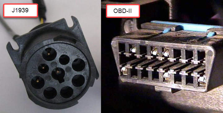
It is more likely that your vehicle has the standard OBD-II port, as the J1939 port is typically reserved for large trucks, farm equipment, and construction equipment. We are going to focus on the OBD-II. To connect a computer or laptop to an OBD-II you will need a USB-2-CAN device and software capable of interpreting the packets on the CAN Bus. Craig Smith, Research Director of Transportation Security at Rapid7, published a phenomenal book, “The Car Hackers Handbook”, that covers interaction with the CAN bus, hardware needed, packet injection, and more!
Now that you know how to create your own test bed and connect into the CAN Bus, you can begin reversing and experimenting with the car's electrical components. For more on this, see the resources section below.
Resources
Here are some good videos on YouTube to get started with:
https://www.youtube.com/watch?v=zwNJocB-y1Y
https://www.youtube.com/watch?v=ZHaxv-cGZFI
https://www.youtube.com/watch?v=U1yecKUmnFo
Other Resources:
- Car Hackers Handbook, Craig Smith (ISBN-13: 978-1593277031)
- OpenGarages.org – http://www.opengarages.org/
- Wilson's Database - http://www.wilsonautoelectric.com/TSBDatabase
标签:Building,Development,Workbench,wires,power,will,circuit,vehicle,your 来源: https://www.cnblogs.com/dhcn/p/15662451.html
本站声明: 1. iCode9 技术分享网(下文简称本站)提供的所有内容,仅供技术学习、探讨和分享; 2. 关于本站的所有留言、评论、转载及引用,纯属内容发起人的个人观点,与本站观点和立场无关; 3. 关于本站的所有言论和文字,纯属内容发起人的个人观点,与本站观点和立场无关; 4. 本站文章均是网友提供,不完全保证技术分享内容的完整性、准确性、时效性、风险性和版权归属;如您发现该文章侵犯了您的权益,可联系我们第一时间进行删除; 5. 本站为非盈利性的个人网站,所有内容不会用来进行牟利,也不会利用任何形式的广告来间接获益,纯粹是为了广大技术爱好者提供技术内容和技术思想的分享性交流网站。